CCD camera selection and classification
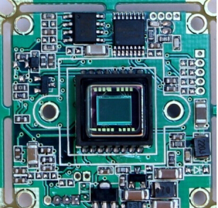
Most of the cameras on the market use chips produced by companies such as SONY, SHARP, Panasonic, and LG in Japan, and now South Korea has the ability to produce them, but the quality is inferior. Because the chip produces different grades during production, different manufacturers get access to different reasons, resulting in CCD collection effect is also very different. At the time of purchase, you can use the following methods to detect: turn on the power, connect the video cable to the monitor, close the lens aperture, see if there are bright spots when the image is all black, and the snow on the screen is not big, these are the most simple and straightforward to detect the CCD chip. Method, and does not require other special instruments. Then you can open the aperture to see a still life. If it is a color camera, it is best to take a colorful object and see if the image on the monitor is color cast, distorted, and whether the color or grayscale is smooth. A good CCD can restore the color of the scene so that the object looks clear and natural. The image of the defective product will have a color cast. Even if it is faced with a blank sheet, the image will show blue or red. Some CCDs have impurities on the CCD target surface due to the dust in the production floor. Under normal circumstances, impurities will not affect the image, but in low-light or microphotographing, fine dust can also cause undesirable results if used. Such work must be carefully selected.
a. Divide the color camera according to the image color: apply to the details of the scene to distinguish, such as the color of clothing or scenery.
Black-and-white camera: Suitable for areas where lighting is not sufficient and where lighting equipment cannot be installed at night. Black-and-white cameras can be used to monitor only the location or movement of the subject.
b. According to the resolution sensitivity, the image pixels are 380,000 or less divided into the general type, in which the 250,000-pixel (512*492), 400-line resolution product is the most common. More than 380,000 high-resolution image pixels.
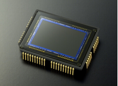
c. Dividing the CCD chip by the size of the CCD target surface A variety of sizes have been developed: most of the currently used chips are 1/3" and 1/4". When purchasing a camera, especially when there are relatively strict requirements on the camera angle, the size of the CCD target surface and the cooperation of the CCD and the lens will directly affect the size of the viewing angle and the clarity of the image. 1 inch - target size is 12.7mm wide * 9.6mm high, 16mm diagonal. 2/3 inch - target size is 8.8mm wide * 6.6mm high, 11mm diagonal. 1/2 inch - target size is 6.4mm wide * 4.8mm high, 8mm diagonal. 1/3 inch - target size is 4.8mm wide * 3.6mm high, 6mm diagonal. 1/4 inch - target size is 3.2mm wide, 2.4mm high, and 4mm diagonal.
d. The PAL system is divided according to the scanning system. The NTSC system adopts the interlaced scanning (PAL) format (CCIR in black and white). The standard is 625 lines and 50 fields. Only non-standard systems are used in medical or other professional fields. In addition, Japan has NTSC format, 525 lines, and 60 fields (black and white EIA).
e. 110VAC divided by power supply (NTSC is mostly of this type), 220VAC, 24VAC. 12VDC or 9VDC (microcameras are mostly such).
f. Synchronously divide the internal synchronization: Use the synchronization signal generated by the synchronization signal generation circuit in the camera to complete the operation.
External synchronization: Use an external synchronization signal generator to send the synchronization signal to the camera's external synchronization input.
Power synchronization (linelock): Use the camera AC power to complete vertical push synchronization.
External VD synchronization: Synchronize the VD sync pulse on the camera signal cable to complete the external VD synchronization.
Synchronization of multiple cameras: Synchronize multiple cameras synchronously so that each camera can work under the same conditions. Because each camera is synchronized, even if one of the cameras is switched to other scenes, the screen of the synchronous camera will not distortion.
g, divided by the degree of CCD is divided into:
Illumination 1~3LUX for normal work
Moonlight type of work required for normal illumination 0.1LUX or so Starlight type of work required for illumination 0.01LUX The following infrared type uses infrared light illumination, can also be imaged in the absence of light h. By appearance:
Organic plate type, pinhole type, hemispherical type.
CCD camera installation and adjustment
a. The lens installation method is C type and CS type two, both threads are 1 inch 32 teeth, a diameter of 1 inch, the difference is that the distance of the lens from the CCD target surface is different, the C type mount from the reference plane to The distance of the focal point is 17.562 millimeters, one more than the distance of the CS type distance CCD target plane, the length of CS type is 12.5 millimeters from the focal point. Do not underestimate this one ring, if you do not have it, the lens and camera can not focus properly, the image becomes blurred. Therefore, before installing the lens, first look at the camera and the lens is not the same interface, if not, you need to increase or decrease the ring according to the specific circumstances. Some cameras do not need to be connected to the ring, but use the rear image adjustment ring (such as Panasonic products), adjust, use a screwdriver to loosen the screw on the adjustment ring, turn the adjustment ring, then the CCD target surface will be relative to the installation base back (front) Sports also play a role in the circle. In addition (such as SONY, JVC) uses a similar way like the adjustment ring, and its fixing screws are generally on the side of the camera. After loosening, adjusting one of the top gears can also make the image clear without adding or subtracting collars.
b. AGCON/OFF (automatic gain control)
There is a video amplifier in the camera that amplifies the signal from the CCD to a level that can be used. The amplification, that is, the gain, is equivalent to a higher sensitivity. However, in a bright light environment, the amplifier will be overloaded and the video signal will be distorted. When the switch is ON, the lens aperture is fully opened under low-light conditions, and the gain is automatically increased to obtain a clear image. When the switch is OFF, a natural, low-noise image can be obtained at low brightness.
c.ATWON/OFF (automatic white balance):
When the switch is turned ON, the characteristic/color temperature of the light source is detected by the lens, so that the white level is automatically set continuously, and the gain of the red and blue signals can be controlled even if the characteristic/color temperature is changed.
d.ALC/ELC (automatic brightness control/electronic brightness control)
When ELC is selected, the electronic shutter continuously and automatically changes the exposure time of the CCD image sensor according to the brightness of the incident light (usually adjusted continuously from 1/50 to 1/10000 seconds). When this option is selected, the ALC auto iris lens can be replaced with a fixed or manual iris lens.
It should be noted that in outdoor or bright environments, because of the limited range of ELC control, ALC lenses should be selected; under certain unique lighting conditions, the following situations may occur:
There is a strong smear or blurring on high-brightness objects such as spotlights or windows.
The image flickers significantly and the color reproducibility is unstable.
There is a periodic change in white balance, and if this happens, ALC lenses should be used.
e.BLCON/OFF (backlight compensation switch)
When powerful and useless background lighting affects the definition of important objects in the middle, the switch should be set to the ON position. Note: 1 When used with a pan/tilt head or when the lighting is rapidly changing, it is recommended to set this switch to the OFF position because the aperture speed of the lens becomes slower when in the ON position; 2 If the desired object is not in the middle of the image, the backlight compensation may not be Will fully play its role.
f.LL/INT (synchronous selector switch)
This switch is used to select the camera synchronization mode, INT is internal synchronization 2,1 interlaced synchronization; LL is power synchronization. Some cameras also have an LLPHASE power sync phase controller. When the camera is used in the power synchronization state, the device can adjust the phase of the video output signal and the adjustment range is approximately one frame. (adjustment requires professionals)
g.VIDEO/DC (lens control signal selection switch)
There are two types of control signals for the ALC auto iris lens. When an auto iris lens with a DC control signal needs to be mounted on the camera, the DC position should be selected. When an auto iris lens requires a video control signal, the VIDEO position should be selected.
When ALC auto iris video is selected to drive the lens, there will also be a video level control (VIDEOLEVELL/H) that may need to be adjusted. This controller adjusts the control level output to the auto iris lens to control lens aperture opening and closing. (recessed light).
In the camera's accessories, there is a black small plug, the plug has four pins, connected to the black socket on the camera. If you use a DC-powered auto iris lens, the lens is ready to plug, just plug in the socket, the selector switch can be set to DC; if you use video-driven auto iris lens, you need the user to use according to the instructions on the instructions, with Soldering iron is good. Since the manufacturer's definition is different, the welding method is also different. Please pay attention to the installation.
h.SOFT/SHARP (detail level selection switch)
This switch is used to adjust whether the output image is sharp (SHARP) or smooth (SOFT). It is usually set at the SHARP position.
i.FLICKERLESS (no flash mode)
In areas where the power supply frequency is 50 Hz, the CCD accumulation time is 1/50 second. If a NISC camera is used, the vertical synchronization frequency is 60 Hz. This will cause the visual image to be out of sync and flicker on the monitor; otherwise, in the power supply This is also the case with PAL cameras for 60Hz regions. In order to overcome this phenomenon, a non-flash mode file is set in the electronic shutter, providing 1/100 second to the NISC standard camera, and a fixed shutter speed of 1/120 second to the PAL camera to prevent the image from flickering on the monitor. Manual electronic shutter: Some users use the CCD to capture objects that move at a faster speed. If they are shot at the end of 1/50th of a second, smearing may occur, which seriously affects the image quality. Some cameras give a manual electronic shutter, so that the charge coupling speed of the CCD is fixed at a certain value, such as 1/500, 1/1000, 1/2000 second, etc. At this time, the charge coupling speed of the CCD is increased, so that the collected Images are relatively less likely to smear, and this setting must be used for observing objects such as high-speed motion or sparks. So, some special cameras give manual electronic shutters for special-purpose users. Manual electronic shutter adjustment need to refer to the random instructions, not repeat them here.
Most of the cameras on the market use chips produced by companies such as SONY, SHARP, Panasonic, and LG in Japan, and now South Korea has the ability to produce them, but the quality is inferior. Because the chip produces different grades during production, different manufacturers get access to different reasons, resulting in CCD collection effect is also very different. At the time of purchase, you can use the following methods to detect: turn on the power, connect the video cable to the monitor, close the lens aperture, see if there are bright spots when the image is all black, and the snow on the screen is not big, these are the most simple and straightforward to detect the CCD chip. Method, and does not require other special instruments. Then you can open the aperture to see a still life. If it is a color camera, it is best to take a colorful object and see if the image on the monitor is color cast, distorted, and whether the color or grayscale is smooth. A good CCD can restore the color of the scene so that the object looks clear and natural. The image of the defective product will have a color cast. Even if it is faced with a blank sheet, the image will show blue or red. Some CCDs have impurities on the CCD target surface due to the dust in the production floor. Under normal circumstances, impurities will not affect the image, but in low-light or microphotographing, fine dust can also cause undesirable results if used. Such work must be carefully selected.
a. Divide the color camera according to the image color: apply to the details of the scene to distinguish, such as the color of clothing or scenery.
Black-and-white camera: Suitable for areas where lighting is not sufficient and where lighting equipment cannot be installed at night. Black-and-white cameras can be used to monitor only the location or movement of the subject.
b. According to the resolution sensitivity, the image pixels are 380,000 or less divided into the general type, in which the 250,000-pixel (512*492), 400-line resolution product is the most common. More than 380,000 high-resolution image pixels.
c. Dividing the CCD chip by the size of the CCD target surface A variety of sizes have been developed: most of the currently used chips are 1/3" and 1/4". When purchasing a camera, especially when there are relatively strict requirements on the camera angle, the size of the CCD target surface and the cooperation of the CCD and the lens will directly affect the size of the viewing angle and the clarity of the image. 1 inch - target size is 12.7mm wide * 9.6mm high, 16mm diagonal. 2/3 inch - target size is 8.8mm wide * 6.6mm high, 11mm diagonal. 1/2 inch - target size is 6.4mm wide * 4.8mm high, 8mm diagonal. 1/3 inch - target size is 4.8mm wide * 3.6mm high, 6mm diagonal. 1/4 inch - target size is 3.2mm wide, 2.4mm high, and 4mm diagonal.
d. The PAL system is divided according to the scanning system. The NTSC system adopts the interlaced scanning (PAL) format (CCIR in black and white). The standard is 625 lines and 50 fields. Only non-standard systems are used in medical or other professional fields. In addition, Japan has NTSC format, 525 lines, and 60 fields (black and white EIA).
e. 110VAC divided by power supply (NTSC is mostly of this type), 220VAC, 24VAC. 12VDC or 9VDC (microcameras are mostly such).
f. Synchronously divide the internal synchronization: Use the synchronization signal generated by the synchronization signal generation circuit in the camera to complete the operation.
External synchronization: Use an external synchronization signal generator to send the synchronization signal to the camera's external synchronization input.
Power synchronization (linelock): Use the camera AC power to complete vertical push synchronization.
External VD synchronization: Synchronize the VD sync pulse on the camera signal cable to complete the external VD synchronization.
Synchronization of multiple cameras: Synchronize multiple cameras synchronously so that each camera can work under the same conditions. Because each camera is synchronized, even if one of the cameras is switched to other scenes, the screen of the synchronous camera will not distortion.
g, divided by the degree of CCD is divided into:
Illumination 1~3LUX for normal work
Moonlight type of work required for normal illumination 0.1LUX or so Starlight type of work required for illumination 0.01LUX The following infrared type uses infrared light illumination, can also be imaged in the absence of light h. By appearance:
Organic plate type, pinhole type, hemispherical type.
CCD camera installation and adjustment
a. The lens installation method is C type and CS type two, both threads are 1 inch 32 teeth, a diameter of 1 inch, the difference is that the distance of the lens from the CCD target surface is different, the C type mount from the reference plane to The distance of the focal point is 17.562 millimeters, one more than the distance of the CS type distance CCD target plane, the length of CS type is 12.5 millimeters from the focal point. Do not underestimate this one ring, if you do not have it, the lens and camera can not focus properly, the image becomes blurred. Therefore, before installing the lens, first look at the camera and the lens is not the same interface, if not, you need to increase or decrease the ring according to the specific circumstances. Some cameras do not need to be connected to the ring, but use the rear image adjustment ring (such as Panasonic products), adjust, use a screwdriver to loosen the screw on the adjustment ring, turn the adjustment ring, then the CCD target surface will be relative to the installation base back (front) Sports also play a role in the circle. In addition (such as SONY, JVC) uses a similar way like the adjustment ring, and its fixing screws are generally on the side of the camera. After loosening, adjusting one of the top gears can also make the image clear without adding or subtracting collars.
b. AGCON/OFF (automatic gain control)
There is a video amplifier in the camera that amplifies the signal from the CCD to a level that can be used. The amplification, that is, the gain, is equivalent to a higher sensitivity. However, in a bright light environment, the amplifier will be overloaded and the video signal will be distorted. When the switch is ON, the lens aperture is fully opened under low-light conditions, and the gain is automatically increased to obtain a clear image. When the switch is OFF, a natural, low-noise image can be obtained at low brightness.
c.ATWON/OFF (automatic white balance):
When the switch is turned ON, the characteristic/color temperature of the light source is detected by the lens, so that the white level is automatically set continuously, and the gain of the red and blue signals can be controlled even if the characteristic/color temperature is changed.
d.ALC/ELC (automatic brightness control/electronic brightness control)
When ELC is selected, the electronic shutter continuously and automatically changes the exposure time of the CCD image sensor according to the brightness of the incident light (usually adjusted continuously from 1/50 to 1/10000 seconds). When this option is selected, the ALC auto iris lens can be replaced with a fixed or manual iris lens.
It should be noted that in outdoor or bright environments, because of the limited range of ELC control, ALC lenses should be selected; under certain unique lighting conditions, the following situations may occur:
There is a strong smear or blurring on high-brightness objects such as spotlights or windows.
The image flickers significantly and the color reproducibility is unstable.
There is a periodic change in white balance, and if this happens, ALC lenses should be used.
e.BLCON/OFF (backlight compensation switch)
When powerful and useless background lighting affects the definition of important objects in the middle, the switch should be set to the ON position. Note: 1 When used with a pan/tilt head or when the lighting is rapidly changing, it is recommended to set this switch to the OFF position because the aperture speed of the lens becomes slower when in the ON position; 2 If the desired object is not in the middle of the image, the backlight compensation may not be Will fully play its role.
f.LL/INT (synchronous selector switch)
This switch is used to select the camera synchronization mode, INT is internal synchronization 2,1 interlaced synchronization; LL is power synchronization. Some cameras also have an LLPHASE power sync phase controller. When the camera is used in the power synchronization state, the device can adjust the phase of the video output signal and the adjustment range is approximately one frame. (adjustment requires professionals)
g.VIDEO/DC (lens control signal selection switch)
There are two types of control signals for the ALC auto iris lens. When an auto iris lens with a DC control signal needs to be mounted on the camera, the DC position should be selected. When an auto iris lens requires a video control signal, the VIDEO position should be selected.
When ALC auto iris video is selected to drive the lens, there will also be a video level control (VIDEOLEVELL/H) that may need to be adjusted. This controller adjusts the control level output to the auto iris lens to control lens aperture opening and closing. (recessed light).
In the camera's accessories, there is a black small plug, the plug has four pins, connected to the black socket on the camera. If you use a DC-powered auto iris lens, the lens is ready to plug, just plug in the socket, the selector switch can be set to DC; if you use video-driven auto iris lens, you need the user to use according to the instructions on the instructions, with Soldering iron is good. Since the manufacturer's definition is different, the welding method is also different. Please pay attention to the installation.
h.SOFT/SHARP (detail level selection switch)
This switch is used to adjust whether the output image is sharp (SHARP) or smooth (SOFT). It is usually set at the SHARP position.
i.FLICKERLESS (no flash mode)
In areas where the power supply frequency is 50 Hz, the CCD accumulation time is 1/50 second. If a NISC camera is used, the vertical synchronization frequency is 60 Hz. This will cause the visual image to be out of sync and flicker on the monitor; otherwise, in the power supply This is also the case with PAL cameras for 60Hz regions. In order to overcome this phenomenon, a non-flash mode file is set in the electronic shutter, providing 1/100 second to the NISC standard camera, and a fixed shutter speed of 1/120 second to the PAL camera to prevent the image from flickering on the monitor. Manual electronic shutter: Some users use the CCD to capture objects that move at a faster speed. If they are shot at the end of 1/50th of a second, smearing may occur, which seriously affects the image quality. Some cameras give a manual electronic shutter, so that the charge coupling speed of the CCD is fixed at a certain value, such as 1/500, 1/1000, 1/2000 second, etc. At this time, the charge coupling speed of the CCD is increased, so that the collected Images are relatively less likely to smear, and this setting must be used for observing objects such as high-speed motion or sparks. So, some special cameras give manual electronic shutters for special-purpose users. Manual electronic shutter adjustment need to refer to the random instructions, not repeat them here.
Zhejiang Changxing Senda Bamboo & Wood Products Co.,Ltd , https://www.sendaflooring.com