Parts that are similar in shape but are not exactly the same size are often encountered in the design, such as serialized product parts, commonly used standard parts, and the like. The two-dimensional design of these parts is now relatively mature. However, with the development of CAD/CAM technology, there has been a new development in the design and manufacture of products, that is, from 3D to 2D design steps, that is, first to establish a 3D model, and then automatically generate 2D engineering drawings, or use The 3D part model directly generates the NC code to achieve no-drawing processing, saving time and cost. Therefore, the establishment of a three-dimensional parametric model of the part is particularly important. It will enable the serialization of the structural design of the product, and greatly shorten the structural design cycle and reduce the workload brought to the engineer due to the dimensional changes of the part.
First, the principle of establishing a table driven part model library
In the serial design process of the product, in order to speed up the product design process and reduce repetitive labor, a three-dimensional model library with the same structural shape and only different dimensions should be established, such as screws, bolts, nuts, washers, seals, lubrication parts and Some standard parts such as bearings. Although UG provides many secondary development tools (such as UG/Open GRIP, UG/Open API and UG/Open, etc.), the use of secondary development tools requires designers to have relatively high technology, which is difficult for designers to complete. Using the table-driven technology provided by UG, it is also possible to create a 3D model library of standard parts, general parts, and product serial design.
After building the 3D parametric model, set the design variables and assign the design variables to the model, then create an external spreadsheet containing these variables to link the spreadsheet to the current model. Because the variables in the spreadsheet are referenced by the part size of the current drawing file, this table can be used to change the size of the part in the current drawing file, so the user can modify the part by controlling the external spreadsheet, avoiding the design. The changes have to modify the losses caused by a large number of model parameters, and a model can be used to express multiple parts of the same structure.
Second, establish a three-dimensional parametric model of table-driven parts
1. Analyze part features
In order to efficiently create a table-driven part, the part must be carefully analyzed before design. First, the general idea of ​​modeling the part should be formed as a whole, and the characteristics of the part to be created and the order in which the feature is created should be clarified. It is also necessary to pay attention to the intrinsic connections of the various features to be created and their respective characteristics, and finally to clarify that the part requires several parameters to drive.

Figure 1 Size constraints of the part
In order to realize the parametric design of the 3D model, the size and geometric constraints of the part are first determined to determine the unique part shape. As shown in Figure 1, the part requires 8 dimensional constraints and some geometric constraints. The size constraints are shown in Figure 1. The geometric constraint includes: four straight lines in the top view are tangent to the adjacent arcs; three circles or arcs having a diameter of 25 mm, 40 mm, and a radius of 28 mm are the same center; a circular arc having a radius of 15 mm and a circle having a diameter of 16 mm; The center line of a circle with a diameter of 16 mm is level. Through the above dimensional constraints and the establishment of geometric constraints, the uniqueness of the parts is guaranteed.2. Create a part model
Based on the analysis of the parts, various features required for the 3D parametric model, including geometric features and auxiliary features, are created according to the respective characteristics of the parts, and the 3D model of the part is completely constrained by all the constraints of the above analysis.
3. Create and assign design variables
UG provides the ability to establish a relationship between the drive size and the model of the part through expressions. Before the table driver is created, the determined design variables are assigned to the corresponding sizes by the rename expression, as shown in FIG. 2 and FIG. 3. The constraint size is re-edited in UG, thus completing the assignment of design variables.

Figure 2 Assigning design variables
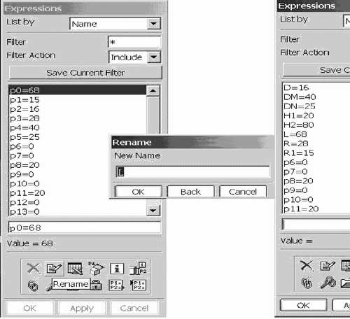
Figure 3 Rename the expression
Next page
Car Stickers,Reflective Tape Sheet,Conspicuity Tape
Caiyuan Reflecting Material Co., Ltd. , http://www.cnreflecting.com