Whether it is a conventional photovoltaic power station built on open plains or a mountain photovoltaic power station with relatively complex topography, grounding is of great significance. Grounding can introduce the current generated by lightning strikes into the earth, thereby protecting the photovoltaic plant's electrical equipment and buildings, and at the same time protecting the personal safety of workers. This article mainly analyzes the part of the grounding design of the photovoltaic power station site.
The grounding of the photovoltaic field area is usually directly using the aluminum alloy frame around the battery plate of the power station cell array as a lightning receiving device, and the metal supporting frame is directly connected with the ground network. Between the metal parts should ensure reliable connection.
Part of the grounding design of photovoltaic power station site is based on the following criteria:
"AC Electrical Installation Grounding Design Specification" (GB50065-2011);
"Design Specification for Overvoltage Protection and Insulation Coordination of AC Electrical Installations" (GBT 50064-2014);
"Overvoltage Protection and Insulation Coordination for AC Electrical Installations" (DL/T 620-1997).
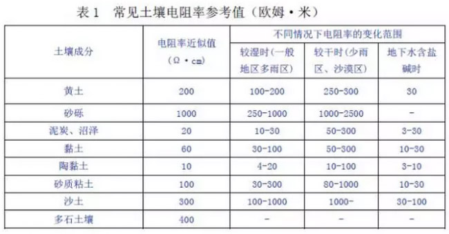
According to the above specifications, the grounding resistance value of the photovoltaic components in the field part of the photovoltaic power station shall not exceed 4Ω. Common soil resistivity reference values ​​are shown in the table below.
In the grounding design, the grounding resistance is calculated based on the local soil resistivity in the ground investigation report, and the calculated grounding resistance must meet the specification requirements.
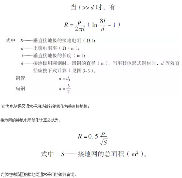
Here are some commonly used grounding resistance calculation formulas.
If the calculated grounding resistance does not meet the regulatory requirements, then it is usually necessary to take certain resistance reduction measures. Resistance reduction measures include: soil replacement method, epitaxial drop resistance method, deep well three-dimensional ground network method, expanded network method, underwater grounding network method, resistance reducing agent method, and installation of electrolytic ground electrode ion grounding body or grounding module. The following describes two types of resistance reduction measures that are frequently used in grounding design of PV power stations.
1, change the soil method:
Change soil method, as the name suggests, is to replace soil with high soil resistivity with soil with low resistivity. According to the common soil resistivity reference table, it can be seen that clay, clay, peat and other soils have low resistivity, and such soils can be used as replacements. Filling soil is a convenient, cheap and effective method. However, if there is no soil around the soil with low electrical resistivity, and the cost of earth moving is too high, then it is necessary to make a technical and economic comparison.
2, epitaxial drop resistance method:
This kind of resistance-reduction method is very simple. It directly expands the area of ​​the grounding grid, or finds a place with a lower resistivity in the vicinity of a built-in grounding net, builds a new grounding net, and then connects the two grounding nets. It is a very simple and relatively economical method to reduce the grounding resistance of the ground network. However, the scope of land acquisition in the photovoltaic field must also be considered during the design process.
To sum up, during the implementation of the project, local geological conditions and other factors should also be taken into consideration, and a technical and economic comparison should be conducted to select a proper one or more combination of drag reduction methods for grounding design.
In addition to the grounding resistance, the grounding portion of the photovoltaic power plant site must be designed with consideration of the following.
First, the laying of grounding nets.
When the grounding net is to be laid, the outer edge of the grounding net should be closed, and the corners of the outer edge should be rounded. The radius of the arc should not be less than half the spacing between the equalizing belts. The buried depth of grounding grid should not be less than 0.6m. If it is in permafrost areas, deep burial methods, soil changing methods, preheating methods, soil property methods, ambient environment methods, special material methods, etc. can be used. Under normal circumstances, the deep-buried method is used, that is, the grounding electrode and the grounding net are laid under the frozen soil layer. The grounding grid can be either long hole mesh or square hole mesh (usually 5m x 5m).
Second, the local soil corrosion.
In areas with strong corrosion, such as saline and alkaline grounds, suitable countermeasures should be taken for grounded bodies buried in the ground. For example, grounding bodies with strong corrosion resistance or thick galvanized layers are used. In addition, the service life of the grounding device should be equivalent to that of the main engineering design.
The above are some of the experiences and conclusions of the author's personal work. Members are welcome to leave a message for discussion.
- Fire resistance - Steel is inherently a noncombustible material. However,when heated to temperatures seen in a fire scenario, the strength and stiffness of the material is significantly reduced. The International Building Code requires steel be enveloped in sufficient fire-resistant materials, increasing overall cost of Steel Structure buildings.
- Corrosion - Steel, when in contact with water, can corrode, creating a potentially dangerous structure. Measures must be taken in structural steel construction to prevent any lifetime corrosion. The steel can be painted, providing water resistance. Also, the fire resistance material used to envelope steel is commonly water resistant.
- Mold - Steel provides a less suitable surface environment for mold to grow than wood.
Structural Steel Frame,Steel Structure Warehouse,Steel Structure Warehouses,Workshop Structural Steelwork
Foshan TianPuAn Building Materials Technology Co.,Ltd. , https://www.tpa-prefabhouse.com