How to accurately and effectively establish the part information model is the core content of CAD/CAPP/CAM integration. At present, the part information model is based on feature modeling technology. The most common practice is to first build a feature library according to the feature classification, then perform basic feature calls according to the actual needs of the model, and use the Boolean operation between the features to build the part model. There are several shortcomings in this approach.
(1) In order to conveniently construct various complex part models, the feature library contains all the basic features as much as possible, which is currently difficult to do.
(2) The current feature recognition technology is not mature enough. How to effectively manage and control the feature database has certain difficulties.
(3) In the actual part modeling process, it is difficult for the designer to quickly and accurately select the desired feature in a short time, which greatly affects the modeling speed.
(4) The existing feature classification method and mechanical machining method are not one-to-one correspondence. A processing method may correspond to several basic features. According to the principle of the feature and the processing method, it should be stored as a composite feature in the feature. In the library, this is obviously unrealistic, and such contradictions have yet to be resolved.
In view of the above deficiencies, this paper firstly clarifies the connotation of the part information model, and on the basis of analyzing the processing technology of the connecting rod, carries out feature planning and design, and then uses the Destructive Modeling with Feature to directly construct the part model. Furthermore, the part information model is established, instead of following the conventional method of feature classification and modeling, the unity of the feature design and the machining process is successfully achieved, that is, each feature is consistent with each processing method of the link.
Second, feature-based part information model
The feature is a collection unit for the complete expression of part information, which is a combination of certain shape, semantics and abstraction [1]. A complete part model is not only a collection of part data, but also a way to express the various types of data and their relationship to each Other. Only part models based on certain expressions can be effectively accepted by various application systems. The complete part information model should include: management features, shape features, precision features, material features and technical features as shown in Figure 1.
(1) Shape features. Describe the functional geometry information with certain engineering significance, which is divided into main features and auxiliary features. The main feature is used to construct the body shape structure of the part. The auxiliary feature is used to modify the main feature, which is attached to the main feature or to another auxiliary feature. Shape features are the focus of product design and manufacturing personnel, and are the carrier of other information.
(2) Accuracy characteristics. It is used to describe the dimensional tolerances, geometric tolerances and roughness tolerances of the parts. The dimensional and tolerance characteristics are important attributes in connection with design and manufacturing. In the feature design, the dimensional and tolerance characteristics are analyzed and the part information model is directly The dimensional and tolerance features are established to clearly represent the non-geometric properties of the shape features and the interrelationships between the shape features.
(3) Material characteristics. It is used to describe the type code, performance, heat treatment method, surface treatment method and other information of the part material.
(4) Technical characteristics. Used to describe the performance, function, and other information of the part.
(5) Management characteristics. Used to describe the management characteristics of the part, such as part name, designer, design date, quantity, drawing number, version, etc. The geometry/topology information of the part is the basis. The feature layer is the core, and the interconnection between various feature sub-models in the feature layer reflects the semantic relationship between the features, making the feature become a basic unit of the structural part with high-level engineering meaning, thus supporting CAPP, NC programming, processing simulation The need for part data.
Third, the establishment of three-dimensional parts information model
The key to building a part information model is to do a feature planning, as shown in Figure 1. Direct modeling techniques can be used to design structures hierarchically, and corresponding parametric feature modules are built at different levels. Each feature is described by a set of parameters that uniquely determine the feature. Taking the connecting rod in the diesel engine as an example, the modeling method and design steps of the three-dimensional part information model are explained by Pro/ENGINEER software.
3.1 Link function and structure analysis
The connecting rod is an important part of the engine, as shown in Figure 2. It transmits the pressure of the expanding gas acting on the top surface of the piston to the crankshaft to push the crankshaft to rotate, and is driven by the crankshaft to drive the piston to compress the gas in the cylinder. The connecting rod has a complicated structure, and is usually divided into two parts: a connecting rod body and a connecting rod cover at a large end, and the connecting rod shaft is an I-shaped cross section, and gradually becomes smaller from a large head to a small head. If you do not make any feature planning, directly use the feature modeling technology to construct the three-dimensional model of the connecting rod. The modeling is easy to fail, and it is difficult to obtain better results. Because the connecting rod structure is complex, it can be completed without simple feature addition and subtraction.
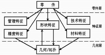
Figure 1 The overall model of the feature-based part information model

Figure 2 Characteristic structure of the connecting rod
3.2 Analysis of the machining process of the connecting rod
The design of the connecting rod features is closely related to the machining. Each processing method corresponds to one feature, which is the basic principle of feature planning. The connecting rod blank is a forged part, and the connecting rod body and the connecting rod cover are integrally forged. The main processing process of the connecting rod is as follows: milling the end of the connecting rod size → drilling the small head hole, expanding to the size value, pulling the small head hole, and ensuring the size and surface roughness value → milling the head positioning boss → cutting from the connecting rod Lower link cover → nut boss on the 锪 link cover, drill the bolt hole, machine the thread → bolt the connecting rod and the connecting rod cover together, and smash the big hole.
3.3 Feature Planning and Design
Through the above analysis of the function, structure and processing characteristics of the connecting rod, the connecting rod model is divided into the feature levels shown in Fig. 2, and the model of the connecting rod is composed of these independent features.
3.4 Feature modeling based on the link of Pro/ENGINEER platform
3.4.1 Entity model
The solid model of the connecting rod in this paper adopts the feature subtractive modeling method. The so-called feature reduction modeling method is to first establish a blank model of the part, and then gradually remove the feature to establish the part model. The following describes the specific modeling process of the connecting rod.
1. The blank forming process of the connecting rod
(1) Determining the parting surface and the drafting angle, and selecting a reasonable parting surface is the first step of rough forging production, so the modeling process should also first determine the parting surface and the drafting angle.
(2) Using the "stretching" method, the blanking model of the connecting rod is generated.
(3) Use the “pull-out†method to generate a draft angle of 7°.
(4) The method of "curved surface cut material" and the function of "rounding" are used to produce the connecting portion in the middle of the link body.
(5) The shape of the large head of the connecting rod is obtained by means of "cutting material".
(6) Using a "cut-cut material" method, a punched skin is formed at the position of the large hole.
The blank of the connecting rod is shown in Figure 3.
2. According to the mechanical processing process of the connecting rod, the connecting rod modeling
(1) Use the “cut-cut material†method to generate large and small end faces to ensure dimensional requirements. The processing of the large and small end faces of the connecting rod is usually the initial procedure of the connecting rod machining process, because this is the main positioning surface of the whole machining process, and its processing quality has an important influence on the processing quality of the entire connecting rod. Therefore, in the modeling process, special attention should be paid to the construction of both ends of the large and small heads.
(2) Select the coaxial "hole" method to generate the small hole and ensure the size and surface roughness.
(3) Generate a large head positioning boss by "rotating and cutting material".
(4) Cut the big end of the connecting rod in the "CUT" way, divide the connecting rod into the connecting rod cover and the connecting rod body, and divide the connecting rod into two parts in order to meet the needs of subsequent processing and assembly.
(5) Thread the bolt boss on the connecting rod cover in the form of “stretching and cutting materialâ€, drill the bolt hole in the “hole†mode, and generate the thread by “spiral scanning and cutting materialâ€.
(6) Bolt the connecting rod and the connecting rod cover together with the bolts. The big hole and the bearing bush and the crankshaft, the small head hole and the piston pin can closely cooperate to reduce the adverse effects of the impact and facilitate the heat transfer. The shape and tolerance of the big hole and the small head hole must be ensured, so the big hole should be built in the shape. Model with small head holes.
At this point, the three-dimensional geometric model of the connecting rod has been established.
3.4.2 Other feature construction
The precision characteristics of the connecting rod are established, and the operation is directly performed on the geometric model by using Pro/ENGINEER. The material features in Pro/ENGINEER are attached to the model in text form. With “Settings†→ “Materialsâ€, material parameters can be defined, modified, deleted, etc. directly in the text file. According to the performance requirements of the connecting rod, the material of the connecting rod is selected as 45# steel. Technical and management features can be added through an external program. Through the above steps, a three-dimensional information model of a part has been completely established, and the part drawing can be automatically generated. Figure 4 is a three-dimensional model of the link generated by modeling.
Fourth, NC program and machining simulation
Pro/ENGINEER offers powerful Pro/NC modules for designing NC machining and manufacturing programs. It can be used to build a 3D machining simulation environment, automatically program the NC machining program, simulate the cutting path of the tool, observe the cutting condition of the workpiece, verify whether overcutting and interference and prediction errors occur, and avoid processing failure. Pro/NC uses image method programming technology for automatic programming, and software-guided programming, so the programming idea is clear. It avoids the interference of various uncertain factors in the manual programming process and avoids human error to the greatest extent. The automatic method of image method is to treat each part of the part process as a set of shape features that make up the part. CAPP is used to connect CAD and CAM information, that is, CAPP can directly receive part information from CAD, generate relevant process specification files, and generate NC code based on this. Using this technology, NC programmers no longer operate on low-level geometric information (such as points, lines, faces, and entities), but instead transform them into NC programming directly for the features that are familiar to engineers and technicians. Programming efficiency. After the NC program is verified, the CL DATA generated by the design and manufacturing program is designed, and the data is converted by Pro/NCPOST, and the NC CODE required for actual processing can be directly obtained.
According to the flow of the Pro/NC design and processing program, the machining process simulation of the connecting rod plane is shown in Fig. 5.

Figure 3 Link blank model
Figure 4 3D information model of the connecting rod

Figure 5 Simulation of the connecting rod machining process
V. Conclusion
In this paper, the characteristics of the connecting rod parts are rationally planned and designed. Based on this, the information model is constructed. The Pro/NC module is used to complete the machining simulation and automatic programming of the connecting rod, and the feature based subtractive modeling method is verified. Correctness, basic integration of the CAD/CAM of the connecting rod, and improved design efficiency.
references
1 Wei Shengmin, Zhu Xilin, ed. Mechanical CAD/CAM [M]. 1st edition. Wuhan: Wuhan University of Technology Press, 2001
2 Wang Xiankun, ed. The application and development of mechanical CAD/CAM technology [M]. 1st edition. Beijing: Mechanical Industry Press, 2001
3 Wang Junxiang, edited by Huang Shengjie. Pro/NC three-axis milling machine processing cheats [M]. 1st edition. Beijing: Mechanical Industry Press, 2001
4 Cai Qing, Gao Guangshou. Visualization, integration, intelligence and networking of CAD/CAM system [M]. Xi'an: Northwestern Polytechnical University Press, 1996
5 Cai Ming, Lin Lanfang, Dong Jinxiang, Yu Jie. Research on Automatic Acquisition Technology of Part Information Model in CAPP System[J]. Journal of Computer-Aided Design & Computer Graphics,2002(5):433~437
Leather Glove,Work Glove,Garden Glove,Synthetic Leather Glove
Rudong Rizhisheng Safety Products Co., Ltd. , http://www.nt-gloves.com