**PLC Installation, Maintenance, and Troubleshooting Issues**
Programmable Logic Controllers (PLCs) are widely used in industrial automation due to their reliability, flexibility, and ease of use. However, proper installation, maintenance, and troubleshooting are essential for ensuring long-term performance and avoiding system failures. This article outlines key considerations for PLC design and application, focusing on common on-site issues that engineers and technicians should be aware of.
**1. PLC Installation**
PLCs are designed for most industrial environments, but they still require specific conditions to operate optimally. Maintaining the right working environment can significantly improve performance and extend the lifespan of the controller. When installing a PLC, avoid the following conditions:
- Ambient temperatures outside the range of 0°C to 50°C.
- Relative humidity above 85% or the presence of condensation caused by temperature fluctuations.
- Direct exposure to sunlight.
- Presence of corrosive or flammable gases such as hydrogen chloride or hydrogen sulfide.
- Dust or metal shavings in the surrounding area.
- Continuous vibrations between 10 Hz and 55 Hz with an amplitude of 0.5 mm (peak-to-peak).
- Impacts exceeding 10 g (gravitational acceleration).
Most small PLCs come with mounting holes at all four corners. They can be installed either by screws or using DIN rails. For screw mounting, ensure the dimensions match the unit’s specifications. For DIN rail installation, first secure the left and right clamps, then mount the PLC and tighten the screws. To protect against environmental factors like dust, oil, and water, it is recommended to install the PLC inside a control cabinet with a protective enclosure.
Proper ventilation is crucial to maintain the operating temperature within acceptable limits. Ensure at least 30 mm of space between the base unit and any expansion modules. If ambient temperatures exceed 55°C, consider adding a cooling fan for forced air circulation.
To reduce electrical interference, keep the PLC away from high-voltage power lines and equipment, maintaining a minimum distance of 200 mm. When mounted vertically, ensure no foreign objects like wire ends or metal shavings fall into the ventilation slots, as this could cause short circuits or damage to the printed circuit board.
**2. Power Connection**
The standard power supply for most PLCs is 220V AC at 50Hz with a tolerance of ±10%. The FX series PLCs also provide a 24V DC output terminal for powering input sensors like photoelectric or proximity switches.
If the power fails for less than 10 milliseconds, the PLC will continue operating normally. However, if the power interruption lasts longer than 10 ms or the voltage drops below acceptable levels, the PLC will stop, and all outputs will be disconnected. Upon power restoration, if the RUN input is active, the PLC will resume operation automatically.
To minimize power line interference, PLCs are equipped with built-in noise suppression. In cases of severe interference, an isolation transformer with a 1:1 ratio can be used to isolate the PLC from ground noise.
**3. Grounding**
Good grounding is essential for both safety and reliable operation. The PLC must be properly grounded to prevent dangerous voltage levels and potential shocks. The grounding wire should connect the machine frame and the base unit. If an extension module is used, its grounding point must be connected to the base unit's ground.
To suppress power and signal interference, the PLC should be connected to a dedicated ground wire. Avoid connecting the PLC ground to the same point as other high-power devices like motors. If a shared ground is necessary, do not connect it in series with other equipment. The grounding point should be as close as possible to the PLC to ensure effectiveness.
**4. 24V DC Input Terminal**
The 24V DC input terminals on the PLC provide power to external sensors. Each input point draws about 7 mA from the internal 24V supply. These terminals can also power external sensors, with the COM terminal serving as the ground.
When using an extension unit, ensure the 24V terminals of both the base and extension units are connected. Never connect an external power source to these terminals. In case of overload, the voltage will drop automatically, and the input point will remain unaffected.
Each PLC has a specified number of input points. Unused points do not consume power, which can increase the available current for external sensors. However, the empty terminals on the FX series PLC must never be used under any circumstances.
**5. Input Wiring**
PLCs typically receive signals from limit switches, sensors, and other contact-based devices. The input terminals act as the interface between the PLC and the external sensors. Input wiring involves connecting the sensors to the PLC’s input ports.
Input devices can be passive contacts or open-collector NPN transistors. When the input is activated, the corresponding LED indicator lights up, confirming the signal is received. Optocouplers are used to isolate the primary and secondary circuits, while RC filters help prevent false triggering due to contact bounce or electrical noise.
If a diode is used in the input circuit, the voltage across it should not exceed 4V. Using two diodes with a reed switch containing an LED is acceptable. Input wiring should not exceed 30 meters, though longer lengths may be used if interference is minimal and voltage drop is negligible.
Avoid using the same cable for input and output signals. Keep them separated to reduce cross-talk. Also, ensure that the pulse width of incoming signals is greater than the PLC’s scan cycle time.
**6. Output Wiring**
PLCs typically offer three types of output: relay, thyristor, and transistor. Output wiring can be either independent or common. When a relay or thyristor is triggered, the corresponding output is activated. Different groups can have varying output types and voltages, but all outputs in the same group must use the same type and voltage.
Since output components are mounted on the PCB, short-circuiting the load can damage the board. Therefore, fuses are often used to protect the output elements.
Relay outputs are suitable for inductive loads, but frequent switching can shorten their lifespan. Transistor and thyristor outputs are more durable for high-speed applications.
Output loads can generate electromagnetic interference, so shielding or filtering may be required. For safety, especially with high-risk loads, an emergency stop circuit should be added to cut off power in case of PLC failure.
Finally, avoid mixing AC and DC output cables. Keep output lines away from high-voltage lines and power cables to prevent interference. If parallel routing is unavoidable, ensure they are not too close together.


Overview
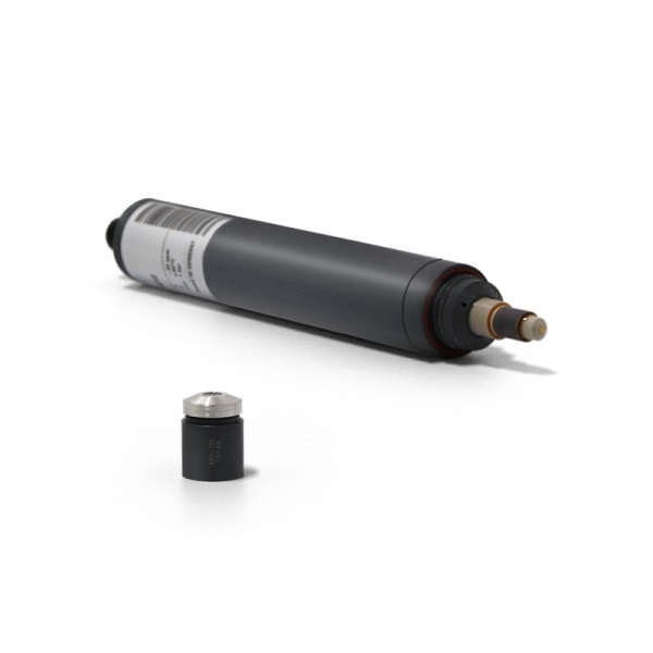
A chlorine dioxide sensor, also known as a chlorine dioxide probe, is a device used to measure the concentration of chlorine dioxide in water or wastewater. These sensors typically operate on the basis of electrochemical principles, utilizing a combination of a working electrode and a reference electrode. The surface of the working electrode is typically coated with materials such as a metal catalyst to enhance the oxidation reaction of chlorine dioxide. When chlorine dioxide comes into contact with the electrode, an electrochemical reaction occurs, generating a current signal. By analyzing the amplitude of this current signal, the chlorine dioxide sensor can accurately determine the concentration of chlorine dioxide present. This technology provides a reliable real-time monitoring solution for various industries.

Â
Chlorine Dioxide: What is It?
Chlorine dioxide (ClO2) is a powerful oxidant known for its robust bactericidal and disinfecting properties. This colorless gas is produced through the reaction between chlorine and chloric acid. Chlorine dioxide's versatility makes it an indispensable compound in various industries. Its primary applications include water treatment, where it effectively eliminates harmful microorganisms, food processing to ensure product safety and shelf life, medical and health sectors for sterilization, and pulp bleaching in the paper industry. Its potent oxidizing ability allows it to work efficiently at lower concentrations compared to other disinfectants, making it both effective and environmentally friendly.
Â
The Importance of Chlorine Dioxide Monitoring
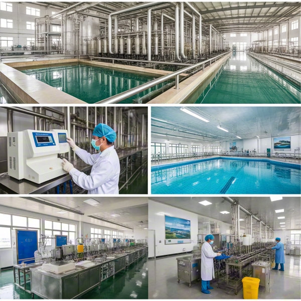
Monitoring the concentration of chlorine dioxide is crucial for several reasons. Firstly, in water treatment facilities, accurate measurement of chlorine dioxide levels ensures that the water supplied for drinking, swimming, and other purposes meets safety standards. This helps prevent the spread of waterborne diseases and maintains the overall quality of water. Secondly, in food processing and medical settings, precise control of chlorine dioxide concentrations is vital to guarantee product safety and sterilization effectiveness. Overuse can lead to unwanted byproducts, while underuse may compromise hygiene and safety. Therefore, continuous monitoring is essential to maintain optimal levels, ensuring the health and safety of consumers and patients.

Â
Daruifuno's Chlorine Dioxide Sensor
Daruifuno offers high-quality Chlorine Dioxide Sensors that are designed to meet the rigorous demands of various applications. Our sensors incorporate advanced electrochemical technology, featuring robust electrodes coated with optimized catalysts for enhanced sensitivity and accuracy. These sensors are engineered to provide reliable and precise measurements of chlorine dioxide concentrations in water, food processing environments, medical facilities, and other critical areas. With a focus on durability and ease of use, Daruifuno's Chlorine Dioxide Sensors ensure consistent performance and long-term reliability. Whether you need to monitor chlorine dioxide levels in municipal water supplies, ensure food safety in processing plants, or maintain sterile conditions in healthcare settings, Daruifuno's sensors offer a trusted solution. Contact us today to learn more about our Chlorine Dioxide Sensors/Probes/Electrodes and how they can benefit your operations.
Chlorine Dioxide Sensor,Chlorine Dioxide Probe,Chlorine Dioxide Electrode
Suzhou Delfino Environmental Technology Co., Ltd. , https://www.daruifuno.com